| |
David C. Rogers
Scientist |
We developed a continuous flow diffusion (CFD) chamber technique for studying ice nucleating aerosol particles in laboratory experiments and from airborne platforms. This page gives some information about the airborne CFD, with plots of the sampling conditions, illustrations of how the CFD was configured in different aircraft, and photos of the CFD. Other information can be found under field projects: Ice Nuclei Measurements in the Arctic and Lake-ICE SnowBand project
Calculations of air flow, temperature, humidity, and particle growth in the space between the two ice-coated walls were first made assuming flat parallel-plate walls and steady-state conditions. Temperature and supersaturation range are determined by wall temperatures and air flow. Two plots are shown, for relatively warm temperatures (-10 to -30°C) and then for colder temperatures (-40 to -60°C).
The profile of air velocity in the CFD chamber is based on analytical solutions for the steady state. This approach is used for real-time operation of the chambers. To understand the evolution of the flow and thermodynamic fields, we are also using computational fluid dynamics modeling. The distance between the walls determines how quickly the air adjusts to the boundary conditions, as illustrated by modeling examples.
| Table of weights and moments of CFD racks in Wyoming King Air | Line drawing of airflow distribution in NCAR Electra during Lake-ICE/SnowBand project. |
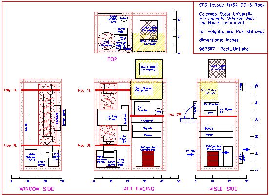
| Drawing of CFD installation in NCAR Electra racks during Lake-ICE/SnowBand project. | Drawing of installation in NASA DC-8 for NASA-SUCCESS project. |
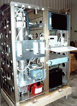
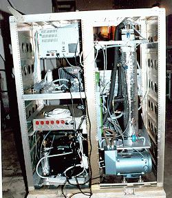
| Photo CFD in DC-8 high rack, front view | Photo rear view of rack |
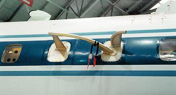
| Photo CSU air sample inlet/outlet on NASA DC-8 | Photo of DC-8 showing many air probes during SUCCESS |
| Photo of Climet optical particle counter | Photo of Climet at CFD outlet |