Computation fluid dynamics studies
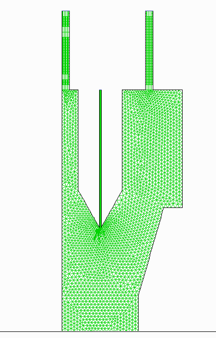
In collaboration with Derek Straub (straub AT roo.susqu.edu), studies are underway, using FLUENT software. The plot on this page shows the 2D computational mesh at top of chamber. In this approximation, the walls are infinitely wide flat plates. The flow is vertically downward. Sheath flow enters through two slits at the top, 4.5 LPM through each slit. Sample air (1 LPM) is injected through the middle of the thin arrow-shaped piece between the sheath flows.The size scales can be estimated from the wall separation, 1.12 cm, at the bottom of the plot. The overall length of the airborne chamber is ~90 cm tall. Only the top 5 cm is shown here. This mesh is based on representing the concentric cylinder geometry of the chamber as parallel planes, which allow simpler calculations.
Here are examples of on-going studies:
- Generation of 3D mesh. This was done by rotating this basic cross section shape about the cylinder center line, replacing the sheath air inlet channels with holes (as in the real chamber), and using a 5º pie-shape segment with periodic boundary conditions.
- Estimate turbulence from the 3D simulation Reynolds number.
- Temperature evolution in the entrance region upper 5 cm, with wall temperatures -15ºC and -30ºC.
- Velocity in the entrance region upper 5 cm showing the non-symmetric profile with faster speeds near the cold (inner) wall.
- Path lines showing sheath air circulation.
- Future - generate a 3D mesh for the outlet region, where the chamber converges between nested cones to a hole.
- Future - trajectories of inert particles 0.5 to 5 Ám
- Future - growth or evaporation of particles