
PLEASE CLICK HERE TO GET TO THE ISS WEB PAGE ON THE NEW EOL WEB SITE
The ISS (Integrated Sounding System) is a self contained meteorological observing system at the Earth Observing Laboratory of the National Center for Atmospheric Research. It consists of a wind profiler radar, radiosonde sounding system, a 10m meteorological tower, solar radiation and other sensors. We can currently deploy up to three ISS.
Recent and Up-coming projects for the ISS include:
- * CHATS where we have our sodar-RASS measuring winds and temperature as part of an experiment to observe micometeorology and the surface and boundary layer around a walnut orchard near Dixon, California (March to June 2007). Sodar-RASS plots are available here
- * CLIMODE where we are on-board the Woodshole research ship, the R/V Knorr, sailing into the Gulf Stream in the North Atlantic in Feburary and March 2007
- * We are in Steamboat Springs during Jan & Feb 2007 for the ISPA-2007 project using our MAPR system.
- * METCRAX at the Meteor Crater, Arizona, October 2006
- * Terrain-induced Rotors Experiment (T-REX) in the Owens Valley, California, March & April, 2006.
- * NAME project at three sites in Mexico, 2004.
- * Sierra Rotors Project in the Owens Valley, California, March & April, 2004.
- * International H2O Project (IHOP) in the Oklahoma panhandle May & June 2002.
- * Reno-2002, an educational project in Reno, NV, March 2002.
- * The ISPA-2001 and ISPA-2002 (Inhibition of Snowfall by Pollution Aerosol) projects at Steamboat Springs, Colorado.
- * IMPROVE-II project in Oregon, 2001.
- * The PROPHET-2000 and PROPHET-2001 projects at the University of Michigan Biological Station, Pellston MI
- * VTMX (Vertical Transport and MiXing) in the Salt Lake Valley, Oct 2000.
- * Nauru99 on-board the R/V Mirai in the central Pacific in June 1999.
- * CASES-99 project in Kansas, 1999.
- * FASTEX on board the R/V Knorr and R/V Suroit in the North Altantic in 1997
ISS Detailed Description
The ISS subsystems are integrated physically and digitally. A Sun workstation is the heart of the digital integration. The Sun is the center of the ISS computer network and serves to collect, display, and archive data from each of the subsystems. The Sun is connected to personal computers in both the radiosonde sounding system and the profiler/RASS sounding system via SAMBA. Data from the surface observing station is routed serially via RS-232 directly into the Sun workstation. The Sun can also format data and control data flow for transmission to sites well removed from the ISS site.
Data transmission from an ISS site can be via modem and phone line or via satellite. In the TOGA COARE project, ISS data from island ISS sites in the Pacific were transmitted to the GOES WEST satellite and ultimately relayed to Boulder, Colorado and other project locations. WMO format GTS messages, both sounding and surface, were transmitted in real time from the TOGA COARE ISS sites. These messages were transmitted via the GOES WEST satellite to forecast centers in real time and incorporated into the forecast models. (Those messages and others were also transmitted to Boulder and then relayed back to Townsville, Australia.)
The balloon borne radiosonde navaid (GPS) sounding system is the standard NCAR "GAUS" sounding system. This sounding system typically uses the Vaisala RS-80 GH which uses GPS satellite navigation signals for wind finding. Launching configurations can vary depending on the installation. An ISS site may have a "bag" launcher, or possibly no launcher at all. The balloon and sonde are secured to structures available before release in the latter case.
The enhanced surface observing station consists of two instrumented towers and a rain gauge. A ten-meter tower is instrumented with wind velocity sensors as well as pressure, temperature, and humidity sensors. A separate one-meter tower is typically instrumented with radiometers. The data are formatted and processed by a Campbell CR10x datalogger. The datalogger is programmable. It is typically configured to generate one-minute average data which are sent via RS-232 to the Sun workstation. Shipboard surface observing station installations require some type of shipboard navaid to correct for ship velocity in the wind velocity measurement.
The 915 MHz wind profiler deployed during TOGA COARE was a three-beam Doppler beam swinging system. The system is now being modified to a five-beam system. The profiler is a long-wavelength Doppler radar which detects the backscattered signals from turbulence-induced refractive index variations. The profiler thus tracks the motion of the turbulent eddies which drift with the mean flow, providing a measurement of the mean wind velocity.
Radial wind velocities are obtained over a variable number of range gates (e.g. 25 to 40) using spectral moment and consensus averaging techniques. Consensus averages can be calculated over varying periods for two vertical modes: one for lower altitude sampling with a high vertical resolution and one for higher altitude sampling with reduced vertical resolution. The raw data are recorded on site in real time to allow for alternative post-processing.
Any shipboard ISS profiler installation requires special attention and adaptation. The microstrip profiler antenna needs to be mounted on a gyro stabilized platform. A three axis accelerometer may be required to measure oscillatory ship motions (backscattered signals are doppler shifted by the motion of the ship) and a GPS receiver is used to determine the speed and heading of the ship. Details of shipboard testing of this system can be found in Carter, et al. (1992).
The radio acoustic sounding system (RASS) utilizes the vertical beam of the profiler to track a broad band acoustic frequency wave front produced by four speakers. (The radar actually tracks refractive index perturbations induced by the acoustic wave traveling at the local speed of sound.) The broad band frequency is used to assure that the Bragg criterion is met. A vertical virtual temperature profile is obtained from the tracking of this wave front (acoustic shell) from the relationship between air density and the propagation velocity (speed of sound) of that wave front.
Vertical virtual temperature profiles with 100 meter resolution can be obtained periodically by the tracking of the generated acoustic signals. A correction can be applied in the real time processing to remove the vertical wind motion from the measured speed of the acoustic shell. Note that the RASS temperature profiles obtained in real time will be drastically affected by hydrometeors. The return from the hydrometeors will invalidate the measurement of vertical wind and the resultant correction will give erroneous profiles. In some cases where there are hydrometeors present, it may be possible to obtain a reliable shell propagation speed in post-processing by using rainfall rate measurements to estimate and remove the hydrometeor fall speeds which would otherwise contaminate the vertical wind measurement.
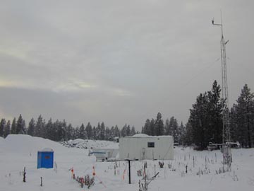
The ISS sites are housed in a standard 20-foot sea container modified to serve as an equipment shelter and laboratory for project scientists and engineers. The modified sea container houses the Sun workstation, the profiler/RASS computer, the balloon borne sounding system computer, as well as storage for expendables, disks, and tapes. The wind profiler and RASS speakers are typically placed on the ground outside of the container. The surface meteorological instrumentation and Campbell datalogger are outside away from the container.
ISS Surface Measurement Instrumentation Description
The ISS surface meteorological instrument installation includes several sensors mounted on two separate towers as well as a rain gauge mounted independently. An anemometer is mounted on the top of a ten-meter tower. Temperature and humidity sensors are mounted on the end of a one-meter boom attached to the ten-meter tower at two meters above the surface. The temperature and humidity sensors are aspirated and protected with a radiation shield. The pressure sensor is housed in the box containing the Campbell CR 10x datalogger. That box is mounted on the ten-meter tower at one meter above the surface and a "pressure port" is connected and mounted at 2 meters. The "pressure port" reduces noise in the pressure sensor do to the venturi effect of from the wind.
The radiation sensors are mounted on a one meter boom on the top of a separate one-meter tower. The standard ISS radiation sensors include an up-looking Eppley PSP solar radiation sensor, Eppley PIR sensor and a net radiation sensor. In situations which require more complete radiation measurements, additional sensors can be added.
The output from all the sensors is directed to the Campbell datalogger for processing. The Campbell datalogger, which is independently programmable, typically generates one-minute average data which are sent via RS-232 to the ISS Sun workstation. The data input to the Campbell datalogger are five-second sample data.
ISS Surface Measurement Instrumentation Specifications
Pressure Measurement
The surface pressure sensor used in the ISS installation is either a Vaisala PTA427 or PTA427A pressure sensor. The PTA427 sensor pressure range is 800 to 1060mb while the PTA427A sensor pressure range is 600 to 1060mb. These sensors have an accuracy of +/- 0.5mb and +/- 0.8mb respectively. They are both silicon capacitive pressure sensors patented by Vaisala. Both are temperature compensated and produce a linear voltage output over the full operating range. In order to interface with the Campbell datalogger, a 2:1 voltage divider is incorporated into the cable from the pressure sensor.
Temperature and Humidity Measurement
The temperature and humidity sensors are contained in a Vaisala 50Y humitter which has been carefully calibrated with a curve fit. The actual sensors are a PRT and a Vaisala "humicap" capacitive relative humidity sensor. The temperature sensor accuracy is +/- 0.4 degrees C over the range -33 to +48 degrees C. The accuracy of the humidity sensor against field references is approximately +/- 2% with a long term stability of better than 1% RH per year. These specifications for accuracy are achieved by internal calibration at EOL and data curve fitting in real time. The 50Y humitter sensor probe is protected and ventilated by an RM Young aspirated radiation shield model number 43-408 and external high flow aspiration fan.
Wind Measurement
Wind speed and direction are measured with an R.M. Young 05103 Wind Monitor. The monitor is a propeller wind vane with a 0.9 m/s threshold for wind speed and a 60 m/s maximum. Wind direction is measured using a 360 degree mechanical precision conductive potentiometer. Direction measurements have a threshold of 1.0 m/s at a 10 degree displacement and 1.5 m/s at a 5 degree displacement. The potentiometer is 10 K-ohm, with a life expectancy of 50 million revolutions and has a 0.25% linearity through the entire range.
Radiation Measurements
The standard ISS radiation measurements are incoming solar radiation and net radiation. The incoming solar radiation measurement is made with a Eppley PSP precision pyranometer. The infrared measurements are made with an up looking Eppley PIR precision PIR pyrgeometer. The net radiation sensor is a Radiation and Energy Balance Systems, Inc. Fritschen net radiometer. The net radiation sensor is a single sensor with up-looking and down-looking hemispheric sensors mounted back-to-back at the end of a 0.5 meter boom.
The Eppley Precision Spectral Pyranometer (PSP) comprises a circular multi-junction wire-wound Eppley thermopile which has the ability to withstand severe mechanical vibration and shock. Its receiver is coated with Parson's black lacquer (non-wavelength selective absorption). This instrument is supplied with a pair of removable precision ground and polished hemispheres of Schott optical glass. Both hemispheres are made of clear WG295 glass which is uniformly transparent to energy between 0.285 to 2.8µm. Please refer to http://www.eppleylab.com/ for specifications.
The PIR comprises a circular multi-junction wire-wound Eppley thermopile which has the ability to withstand severe mechanical vibration and shock. Its receiver is coated with Parson's black
lacquer (non-wavelength selective absorption). Isolation of long-wave radiation from solar short-wave radiation in daytime is accomplished by using a silicone dome. The inner surface of this hemisphere has a vacuum-deposited interference filter with a transmission range of approximately 3.5 to 50 µm. Refer to http://www.eppleylab.com/ for specifications.
The Radiation and Energy Balance Systems, Inc. Fritschen net radiometer, measures the sum of all incoming radiation (direct solar, diffuse solar, longwave skylight) minus the sum of all outgoing radiation (reflected radiation and terrestrial longwave radiation). A single data stream, the difference of incoming and outgoing radiation, is recorded from the Radiation and Energy Balance Systems, Inc. Fritschen net radiometer. The wavelength range of this instrument covers both the shortwave and longwave bands.
When more precise radiation measurements are required, three separate radiation measurements can be made in the surface meteorological installation, shortwave, longwave, and net radiation. Both the shortwave and longwave radiation measurements are then made with pairs of Eppley radiometers, one up-looking and one down-looking radiometer in each pair. The net radiation measurement is again made with the Radiation and Energy Balance Systems, Inc. Fritschen net radiometer.
The shortwave radiation measurements are made with Eppley PSP pyranometers. The wavelength range of these instruments is 0.285 to 2.8 um. Separate data streams are recorded from both the up-looking and down-looking pyranometers. The longwave radiation measurements are made with Eppley pyrgeometers. The wavelength range of these instruments is 3.5 to 50.0 um. As with the pyranometers, separate data streams are recorded from both the up-looking and down-looking pyrgeometers.
Rain Measurement
A Texas Electronics TE525 tipping bucket rain gauge is used at all land based ISS sites for measurement of rainfall. The rain gauge resolution is 0.254 mm. The gauge is typically positioned 1.5 meters above the ground about 7 or 8 meters from the ten-meter tower. Shipboard rain measurements can be made with a Scientific Technology Inc. optical rain gauge, STI ORG-100. These STI rain gauges are currently not available as standard ISS furnished equipment. At present they would have to be purchased by the project. They may become available as standard equipment at a later time as funding permits.
ISS Balloon borne Sounding System Description
The ISS balloon borne sounding system is the standard NCAR "GAUS" sounding system (See Chapter addressing the GAUS system for complete information). The integration of the surface meteorological data into the sounding data is somewhat different in the ISS. In the NCAR ISS configuration, that surface data are made available to the "GAUS" sounding system through the ISS computer network via SAMBA. (The surface data are first transferred from the Campbell datalogger via RS-232 to the ISS Sun workstation.)
Radiosonde Deployment
There are differing launch configurations possible at any ISS site. There can be a "bag" launcher used where a heavy vinyl tarp contains and protects the balloon prior to launch. A "bag" launcher is typically used on shipboard ISS installations. In addition, a site can function without a launcher, in which case, the balloon and sonde are tied outside the ISS container and then released. All releases are environmentally aspirated and shaded from direct sunlight.
ISS Wind Profiler and RASS Specifications
Up to four sets of radar parameters can be defined for the ISS wind profiler and RASS system. These are set up interactively by the operator. The operator enters values for the inter-pulse period (IPP), the pulse width (PW), the number of heights (NHTS), the time from the first transmitted pulse to the first sampled height (DELAY), and the spacing between the sampled heights (SPACE). The four pulse widths available define the vertical resolution of the wind profiler and RASS. Those pulse widths are as follows:
- 400 nS pulse - 60 meter resolution;
- 700 nS pulse - 100 meter resolution;
- 1700 nS pulse - 250 meter resolution;
- 3300 nS pulse - 500 meter resolution.
The pulse width also defines the amount of energy transmitted by the radar and in most cases is reflected in the maximum altitude coverage. Another key factor in altitude coverage is the availability of scatterers to provide refractive index irregularities within the sample volume. Most variations in refractive index depend on the variation of temperature and humidity caused by turbulent eddies that are in a size range on the order of one-half the radar wavelength.
The following tables summarize the wind profiler and RASS system characteristics. Note that on the wind profiler height resolution entries, resolutions are given for two modes, a low altitude mode (high resolution) and a high altitude mode (low resolution). The height to which the profiler can measure wind velocities is highly dependent on the atmospheric characteristics.
TABLE 12 Wind
Profiler Typical Performance Specifications
|
|
| Radar Frequency | 915 MHz |
| Radar Wavelength | 0.33 meters |
| Mean Power | 50.0 W |
| Antenna size | 4.0 square meters |
| Beam Width | 10.0 degrees |
| Minimum Height | 0.12 km AGL |
| Maximum Height | 2 to 5 km AGL |
| Height Resolution | |
| Low altitude mode: | 60 & 100 meters |
| High altitude mode: | 250 & 500 meters |
| Wind Speed | < 1.0 m/s |
| Wind Direction | < 1.0 degree |
TABLE 13 RASS
Specifications
|
|
| Acoustic Frequency | 2000 Hz |
| Acoustic Power: | 400.0 W |
| Total Electrical Input | |
| Acoustic Beamwidth | 8.0 degrees |
Additional Information
ISS Workstation ManualISS Images
Spaced antenna profiler (MAPR)
For more information contact William Brown, Email: wbrown at ucar.edu