Electric
Fields
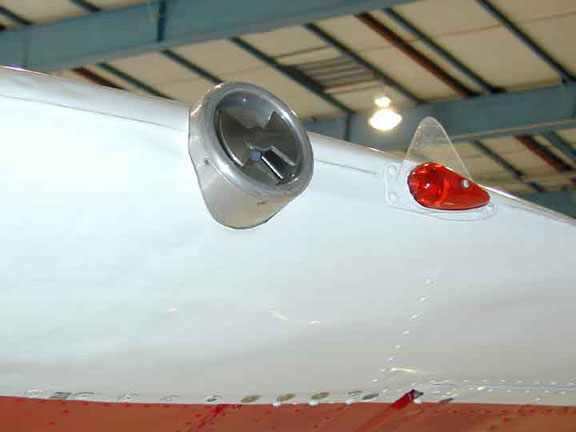
The ambient electric field components in the vertical and horizontal directions, transverse to the aircraft heading can be obtained from a suite of 6 rotating-shatter electric fields meters mounted on the T-28 (one top, one bottom, and 2 on each wing, front and side). Winn (1993) describes these meters. The performance of this system is periodically checked by artificially charging the aircraft in clear-air flight using an on-board high voltage power supply. The equations used to calculate the ambient electric field components usually should produce good results in the absence of interference from the effects of aircraft charging. Mo et al (1999) demonstrate that the aircraft is rarely charged highly, as corona discharge from trailing edges of the propeller and airframe, and discharge wicks placed on the trailing edges, limits buildup of aircraft charge. A more serious problem is the effect of the space charge due to corona discharge from the propeller on the two fuselage meters. Mo et al (1999) discuss how the effects of this charge can be detected and eliminated during calculation of ambient fields from the meter readings. Below we have a picture of the the electric field mill on the port wing tip.