PAR / Wand Notes ...
The prototype PAR wands data acquisition was built around the Crossbow
Mica2 mote running the Mantis Operating System (MOS). NCAR developed an
interface board for the Mica2 with a serial
driver/translator, simple dc-power regulator (LDO) for generating the
required 3.3vdc used by the mote, and an I2C interface connections for actual
interactions with the Wand's themselves.
Power for the wand interfaces was provided by direct connection to an
ADAM that was operating off line power.
Within the wands, a small ADC
board was placed to obtain data from the 3 Photovoltaically Active
Radiometers (PARs) positioned at .1m, .5m, and 1m from the trees. A
level sensor with another ADC was also on the wand board.
PAR Diodes / OpAmps:
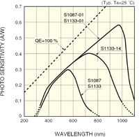
The PhotoSynthetically Active Radiometer (PAR) sensor used was a S1087
($6.70ea) silicon photo diode manufactured by Hamamatsu. A small, inexpensive
device responding to 320nm to 730nm light in the visible spectrum with
peak sensativity at 560nm: Data Sheet
The other Hamamtsu part considered but rejected was the G1118 ($14.50ea
GaAsp). It is more robust than the S1087, but its resin coating
appeared to be a limiting factor in performance, plus cost. Having a
metal cannister though, implies for long-term use, there would be less
UV degradation of the packaging. That concern for the S1087 was
mitigated as follows.
Each PAR diode was interfaced to a small op-amp board used to boost
current source signal levels into the range needed by the ADC used.
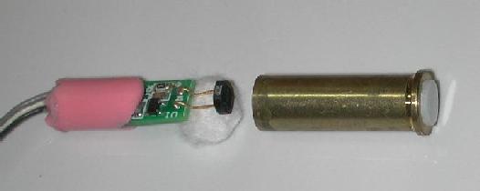
The diode and op-amp board
were installed in a modified 38-special shell casing. A small diffuser
material was added to improve the response to sunlight, especially at
low angles. The diode/op-amp were packed into the casing using cotton
and a synthetic rubber material used for ear plugs. This method allowed
the diodes to be removed easily for repair, while the packing helped
insure good fit between the diode and diffuser and provided water
resistance. This method worked well but resulted in the bullet
assembly protruding beneath the wand itself. A rubber cap was used to
protect the wires and hold the bottom of the shell in place on the
wand. For Production Wands, a more permanent installation method will
be investigated.
In the op-amp circuit below, the gain resistor, R1, was 50-kOhm as determined by direct
measurement in sunlight to ensure that output voltage did not exceed
but had peak output near the full-scale range of the ADC (2.048). A
larger value resulted in too low a signal and a smaller value over drove
the ADC. The OpAmp used was a Texas Instruments TLV2711:
Data Sheet
Three PAR sensors were installed in a Wand; .1m, .5m, and 1m from
the base mounted to the tree. These were attached to a three
channel ADC from Texas Instruments, the ADS1112
( Data Sheet )
mounted on a small board installed in the wand. The wand board also
had another ADS1112 used to sample an analog STMicroelectronics LIS2L02AL
( Data Sheet )
accelerometer to provide level information for the wands when mounted in the
trees. The ADS1112 ADCs were interfaced to the mote via an I2C 2-wire
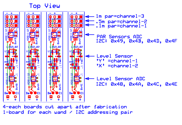
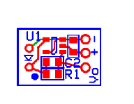
bus. Shown below is a top view of the ADC PCB layout before the individual boards
were cut apart. Four were placed on a single PCB each wired differently for
their I2C addresses: (0x48/0x49, 0x4A/0x4B, 0x4C,0x4D, 0c4E/0x4F).
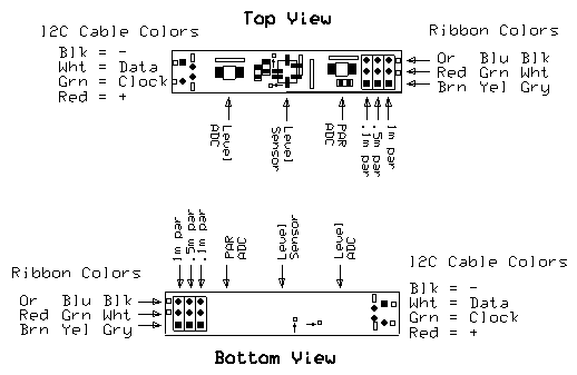
 All wires from the bullets to the wand board had one of three color-coding patterns.
The I2C interface cables were all similar.
 The individual boards were mounted inside the wands to simplify cabling,
construction and minimize the size of board needed attached directly to
the mote. In practise the boards were installed upside-down in the
wands because of restricted space to attach the wires from the PAR
bullets. It was unclear whether having these boards mounted in the
wands reduced overall effort compared to a different solution of having
all the ADC's located with the motes. It did result in shorter analog
signal runs from the PAR though.
Alternative Accelerometers:
Other 'level' sensors were considered, most notably the Memsic Devices
MXC6202 and MXC602 versions. These have an I2C interface which would
have made them ideal for the PAR application. A few prototype test
PCboards were made for testing these parts. Unfortunately they were
considered to have much too high of a temperature drift component to be
satisfactory. Another good alternative was the ADXL204, also prototyped
and evaluated. It's problem was primarily cost: noted below.
Other accelerometers that could be 'in-the-ballpark' (check these
numbers if considering in future!):
| Manuf. |
p/n |
Range |
mV/G |
Voffset |
Acc. |
Packg |
~Cost-Dig. |
| FreeScale |
MMA6270QT |
+/-1.5-6G |
800/400/300/200 |
1.6V |
% |
16qfn |
$8.40 |
| FreeScale |
MMA6260QT |
+/-1.5 |
800 |
1.65V |
% |
16qfn |
$6.37 |
| FreeScale |
MMA6271QT |
+/-2.5- |
480/360/180 |
1.65V |
% |
16qfn |
$5.70 |
| AnalogDevices |
ADXL204 |
+/-1.7 |
620 |
1.65V |
4% |
8LGA |
$19.40 |
| AnalogDevices |
ADXL322 |
+/-2.0 |
420 |
1.5V |
10% |
16LFCSP |
$8.60 |
| VTI |
SCA3000-D02-10 |
+/-2.0 |
I2C:1333/G |
na |
na |
18 |
$27.00 |
| STMicro.Elec. |
LIS302DLTR |
+/-2.0 |
I2C:128/G |
na |
na |
14LGA |
$12.20 |
| STMicro.Elec. |
LIS2L02AL |
+/-2.0 |
Vdd/5 |
Vdd/2 |
% |
8LGA |
$9.20 |
Because prototype testing of Analog Devices ADXL204
was successful though the part was expensive, we decided to evaluate
the LIS2L02 accelerometer/level sensor because it conformed to the same
footprint. These also met acceptance criteria for accuracy and
stability in our initial tests and we decided to use them. However,
their 8LGA package is tricky to solder using an iron because the only
contacts are under the package. This mounting challenge ended up
resulting in a significant number of failures during final assembly of the
wandboards probably due to over-heating with the soldering iron, and/or
imperfect contact. These parts should be satisfactory with another
attachment method, perhaps using solder paste, or oven. STmicro does
offer a technical note about soldering.
Mote Interface Board for Mica2:
Schematic
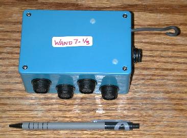
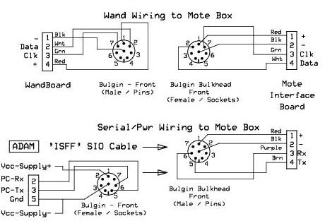
The simple Mica2 interface board built and assembled along with the mote inside
a small nema4x box for mounting in the trees. Four connections were
provided to the outside via 8-pin Bulgin connectors for wand
power and I2C interfaces. A fifth Bulgin connector was used to supply
primary power and serial interfacing with the ADAM.
 The interface board included a Maxim MAX3221 RS232 Transceiver
( Data Sheet )
to allow signal translation for communications between the Mica2 and the
ADAM data system. This feature allowed the mote to be reprogrammed
directly from a PC without needing to rely upon a Crossbow programming
board. Although it was not done, the opportunity existed to change the
mote program while installed in a tree without having to include the
'over-air' programming code available with MOS, saving valuable code space.
The mote interface board included two TPS7603x linear low dropout voltage
regulators (LDO) by Texas Instruments
( Data Sheet ).
One provided the 3.3vdc needed for primary mote operations. The
second was optional (and not used in practise) to provide a lower
voltage to the wands. The rationale for that was to reduce the
dc-offset voltage for the level sensors (1/2 of vsupply, +/-
600mV=90degrees) so that a larger range than ~40 degrees could be
measured by the ADC limited to max 2.048v.
The mote interface board had other features that were not used
during the NIWOT07 PAR deployment: connections for interfacing
Mica2 internal adc channels 2-5, a connection for a Sensiron
SHT15 temp/rh sensor including a switched '+12vdc' FET that was intended to
cycle on/off an aspiration fan, and a connection for mote leds and
reset lines.
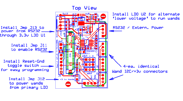
Shown below is the PCB layout of the mote interface board. Note the
jumper options. Also note the temporary labeling used to identify
that this box has calibrations for wand set #7 (see calibrations below).
Mote Software
The MOS base mote software listings are referenced below, as they stood
in August-07 during the actual deployment.
Message Format
Serial PAR data messages were sent every 1-second to the
ADAM from the motes.  The appearance of these messages was:

PAR1st: 982.331 1008.73 970.016 988.128 966.018 941.408 966.663 978.635 970.429 983.607 971.158 961.4120
PAR1st: 980.573 1007.03 968.504 986.331 964.413 939.875 964.909 976.934 968.920 981.845 969.503 959.8586
PAR1st: 979.656 1006.04 967.641 985.396 963.464 939.072 963.994 976.042 968.057 980.964 968.600 959.0481

These fields represent in order (labels for each wand noted):
	wand-0x48, .1m, .5m, 1m
	wand-0x4A, .1m, .5m, 1m
	wand-0x4C, .1m, .5m, 1m
	wand-0x4e, .1m, .5m, 1m
with the values in microMols/sq-Meter/second.
Nominal values would be expected to peak at roughly 2000 or so in full sun.

Interspersed with these messages were Level data every 5-seconds.
The appearance of the Level sensor messages was:

LVL1st:  3.0626 -4.1584  3.9080  6.4149  1.1936 -11.950 11.7497 10.5539

These fields represent in order:
	wand-0x48, Xlevel, Ylevel
	wand-0x4A, Xlevel, Ylevel
	wand-0x4C, Xlevel, Ylevel
	wand-0x4e, Xlevel, Ylevel
with the values 'calibrated' in tenths of degrees
(eek ... I think, not whole degrees!)

The ADAM data system time-tagged each message as received.   There are
slight inaccuracies in these rates due to mote clock/mos timing and my
ability to measure and estimate the 'fudge-factor' for time taken up in
the sampling loop.  I.e. the 'sleep-time' between sample/message output
cycles was adjusted from the desired-rate minus a factor for # sampling
the ADCs and minus a factor for latency of software calibrations and
print timing.
Installation
The PAR wands were deployed in two trees by Russ, Maggie and a student on
Aug.16th,2007 and removed Oct,3rd.    They placed a scaffolding tower between a fir and spruce
tree of interest, and used it for installing the three levels.

Wand Heights:
-------------
ACTUAL: "3.5m", "6.0m", and "8.5m"

but in the original ADAM xml file (in the ADAM) they were denoted "0.5m", "3.5m", and "7m".
These were changed on the server version on 9/24 and covars were rerun.


Wand Orientation:
-----------------
Not exactly oriented to NSEW (see Maggie's notes) but were roughly at:
0x48-x = North; w1
0x4A-x = West;  w2
0x4C-x = East;  w3
0x4E-x = South; w4


ADAM Port Configuration:
-------------------------
Tree-0: Fir, 12.9m tall, 19cm DBH, located to the West of the scaffold.
Port	Actual		Wand#
ttyS5	West.3.5m	wand5	id=100 (Raw), id=101 (PAR) id=102 (LVL)
ttyS6	West.6.0m	wand1	id=110 (Raw), id=111 (PAR) id=112 (LVL)
ttyS7	West.8.5m	wand4 	id=120 (Raw), id=121 (PAR) id=122 (LVL)

Tree-1: Spruce, 11.5m tall, 15.9cm DBH, located to the East of the scaffold
ttyS8	East.3.5m	wand6	id=130 (Raw), id=131 (PAR) id=132 (LVL)
ttyS9	East.6.0m	wand3	id=140 (Raw), id=141 (PAR) id=142 (LVL)
ttyS10	East.8.5m	wand2	id=150 (Raw), id=151 (PAR) id=152 (LVL)

Never Installed due to scaffolding:
t0w3p1-3.3.5m (West Tree, East Wand, lower 2 levels)
t0w3p1-3.6m
t1w2p1-3.3.5m (East Tree, West Wand, lower 2 levels)
t1w2p1-3.6m

Note that because of the scaffold, tree0(on the West side)-3.5m/6m
wands '0x4C-East', and tree1(on the East side)-0.5m,3.5m wands
'0x4A-West'were never installed...


Attachment / Ideas:
--------------------
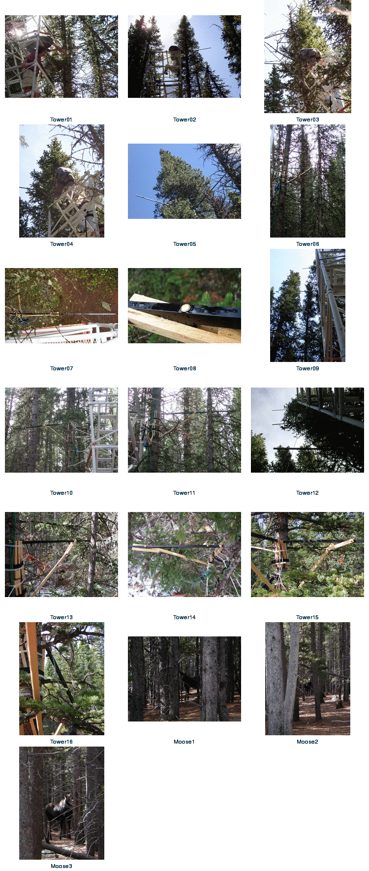
Although the wands themselves were made from aluminum extrusions, they
were braced against the tree with wooden diagonal braces.  The braces
offered a wide range of adjustability for leveling.   Each wand was
strapped with either/both large plastic cable ties and/or nylon webbing
straps in 2-4 locations.   This did provide structural security and the
wands did not move (except when pushed by nearby trees/limbs???),
Click to Enlarge
Ideas:
------

Even with the scaffold tower, the effort required to put four wands on
the tree was awkward and required two people: probably unacceptable for
the 2008 deployment in 9 trees.

Possible alternatives:
	1)  A modified ladder with improved stabilization support on both
	    the ground and tree might be used.   The question with that idea
		is whether the tree would bend too much.   A second ladder or
		something similar on the opposite side may provide enough
		stability, and a second work platform for a second person
	2)  A temporary guyed Rohn tower would be more easily relocated
		than scaffolding, but could be just as awkward to work from.
Power Consumption
These notes may be incomplete due to testing still in progress to
evaluate

Mote Power Switch Note:
	Turn-On to save ~2mA when using the Interface Board!

	For the PAR application, the mote interface board supplies regulated
	3.3v to the mote via the 51pin Hirose inter-board connector. If the
	mote's battery switch is turned off, and extra load is imposed, that
	is not present with the switch on.   The reason is unclear from
	casual inspection of the Mica2 schematic.   It should make no
	difference and I don't have the patience to poke around and see
	what's missing on the schematic from the actual board.

PAR Application: Mote + Interface
	25mA		Continuous 1-sec messages through interface board,
				using best 'mos-sleep' setting, but radio still
				energized.
	26.5mA		With wands attached

	28mA		12.2vin = .60W (initial measurements without best sleep)
	25mA		 5.0vin = .13W
	27mA		 3.3vin = .09W

	11.5mA		 3.3vin = .04W  With radio off.


Mote Interface Board Alone: (whether input is 5 or 12V)
	2.55mA		with MAX3221 energized but not transmitting
	 .10mA		without it.

Efficiency and Limits with the LDO TPS76033:
	The LDO being a linear regulating device has limited efficiency.
	The biggest factor in efficiency is what the input voltage is
	versus the output.   About the same amount of current drawn for the
	output will be supplied by the input, so the higher the input
	the lower the efficiency and the excess heat will need to be
	accomodated.
	VinMax = 13.5V	35microA quiescent	50mA max in SOT23-5 pkg
	This device has junction-over-temperature protection set at 160
	and should recover when it drops.

	MAXIMUM DISSIPATION at 25C=380mW, 70C=212mW, 85C=154mW
	Some devices provide calculations for max.junction temperature
	before shutdown/fail, but with this method, look at the current and
	the input voltages.   If supplying 12 to the PAR mote:
	(12-3.3) * 25mA = 217mW dissipation (300mW supplied, 83mW consumed)

	For the PAR application, I put a 5V DC-DC in the ADAM box
	for driving the motes so it should be OK.:
	(5-3.3) * 25mA ~=  50mW dissipation (125mW supplied, 82mW consumed)

	Efficiency, Crudely: ~= vout/vin ~= 3.3/12.7 = 25%
					 ~= 3.3/5    = 66%

HelloWorld Application (Mote only)
----------------------
	.01mA		Deep sleep with radio off, 1 thread only.
	This was observed while running a quickie program to ascertain the
	utility of the 'currentMonitor': confirming that MOS will
	power down a mica as well as TOS given the same 'operating' mode.


Tsoil Application Comparison
----------------------------

	TinyOS Tsoil Application: Mote only (As run on Niwot04-NCAR)
	--------------
	25.0mA	Transmit (<.5sec,and daq)
	17.3mA	Receive (5sec avg)
	  .05mA	Sleep (25sec avg)
	= 3.1mA	*3.3vdc = .01W Average for 30second cycling

	~= 75mAH/day or 13.5days for 1000mAH battery usage


    Tsoil Mica2: (original readings during some mode tests)
		   13.8mA	With LEDs, RF going
		   11.4mA	(nom. without power-down)
		    2.5mA	w.o LEDs, no RF
		    3.3mA	nominal power during DAQ, no RF
		   < .03mA	with PMEnable() power-down, no RF

	Note:
	    Atmega output pins source 5-10mA
	    Stop Services to have them enter low power mode.
	    	When all services are stopped and Task Que is empty,
		TOS goes into Power Down, and
		Wakes up on next Event from TimerM.nc


	MOS Tsoil Application: Mote only (As run Niwot07-CU)
	--------------
	~5.5mA	Average (as I recall) for 1-minute cycling

	~= 132mAH/day or 7.5 days for 1000mAH battery usage

	NOTE: as of Sep07 these numbers were rough.   Ongoing tests
	by Ramesh and Mike are refining this.  The value
	may be somewhat optimistic given actual observed performance,
	from verbal reports by Lynette and others.  It's likely that the
	more sophisticated algorithm used in their star-radio network caused
	extra radio 'listen' time increasing the value shown above.


Tiny Solar Boxes
----------------
		Blue Boxes with old crystaline pvs:
	    TinyPV Panel:  Isc=~20mA (ea.), Voc~=4.5V	Full Sun

		TravelPal Solar Chargers used for MOS Tsoil
			Isc = 110mA
			Voc = 7.7V
			Ic  = 50-60mA	4NiMh at 5.4V
			Ic	= 15mA		4Alk, fully charged, 6.5V


Mote-MaxStream RF Repeater (Mica2 to Maxstream Radio repeater)
--------------------------
		TOSbase on MIB510:	28mA
		MaxStream, Listen:	54mA
			   Transmit:	88mA
		Total,
		Listen:	 =  82mA @12.7V ~= 1.0 Watt
		Transmit = 105mA @12.7V ~= 1.5 W
Data Handling at NCAR
Niwot07 data was retrieved by hand, swapping USB disks on the adam. This was
adequate for the short '07 deployment but will be replaced by
having the adam on the CU network for 2008.
NOTE: Raw data files generated by the adam are in ext3 format, and cannot be
read on a windows, only linux machines.
Data locations:
/net/isff/projects/NIWOT07/raw_data
| /net/isff/projects/NIWOT07/raw_data |
raw isff file dir, linked to /scr/aster/projects/NIWOT07/raw_data |
| |
on SteveOncley's scratch disk |
| /net/isff/projects/NIWOT07/ISFF/netcdf |
'manually' generated 5-minute covar files |
How to Generate NETCDF Files: statsproc
Standard 5-minute covariances were not generated locally on the ADAM in
part because we didn't think they would be used.   However, they
are easily created at NCAR-FL using the EOL servers.

1) setup environment variables
$ set_project				and chose NIWOT07, and just to make sure...
$ setenv DATAMNT /net/isff
$ setenv RAWDATADIR /net/isff/projects/NIWOT07/raw_data
$ setenv NIWOTXML isff_par.xml

2) load raw data onto server under $DATAMNT/projects/$PROJECT/raw_data

3) run the statsproc
$ set datestr = `utime -L "2007 aug 23 00:00"`
$ echo $datestr
$ statsproc -B $datestr                        uses the 'current' xml
OR explicit xml file:
$ statsproc -x $ISFF/projects/$PROJECT/ISFF/config/isff_par.xml -B "$datestr"

NOTE: the statsproc should grab all of the data files found in the
raw_data dir beginning with the date specified for the first 2 methods,
OR for explicit time window and file:
$ cd /net/isff/projects/NIWOT07/raw_data
$ statsproc -B "2007 aug 16 00:00" -E "2007 aug 31 12:00" par_200708*

5) check the data files
$ nc_dump -h /net/isff/projects/NIWOT07/ISFF/netcdf/isff_20070830.nc

This method generates 5-minute covariances as defined by the xml file.
Using SPLUS to plot 5-minute NETCDF data:
This should probably be run on the EOL-host 'shiraz' which is
intended for numerical applications.

$ Splus7
> cmotif()		bring up display screen
> dpar(start="2007 aug 29 00:00",lenday=2,lenhr=12)
> plot(dat("Rpar"))	yikes there's a whole bunch of variables!

> dpar(hts=8.5)		ok, let's only look at the tree tops
> p = dat("Rpar")
> x = dat("x")
> y = dat("y")
> plot(p[,1:3])		tree0, north wand, 3 sensors
> plot(p[........

0x48-x = North
0x4A-x = West
0x4C-x = East
0x4E-x = South

t0w3p1-3.3.5m (West Tree, East Wand, lower 2 levels)
t0w3p1-3.6m
t1w2p1-3.3.5m (East Tree, West Wand, lower 2 levels)
t1w2p1-3.6m
Results and Observations
Corrosion:
----------

DURING THE DEPLOYMENT, some PAR sensors failed and were examined:

Wand48-5: Maggie retrieved on ~14Sep07, reporting she had seen bad
values.  In the lab, PAR#3 (1m) was pegged out, and PAR#2 appeared to be
reading slighly high, and #1 had bad been showing erroneous data.

There was significant corrosion on the solder joints where the par wires
connect to the ADC board, ie. nearest to the 'tree end of the wand' and
vulnerable to water being blown in.  Upon cleaning, pars #1,#2 came back
to life, but par#3 then read '0' and was unresponsive.

Inside PAR#3's bullet, there was evidence of corrosion on the cotton
packing and it seemed to have moisture on the cotton even after 1-week.
It also had slight corrosion where the wires attach to the op-amp board
and on a diode lead (cathode).  While cleaning the board, that photodiode wire
broke.  This may have been corroded or was weak all along, however, once
reconnected the output was still bad.  In further attempts, the par
diode never recovered, though it is possible that it may have gone bad
during soldering/overheating.  A crummy picture of the par#3 (corrosion
appears brown and was...
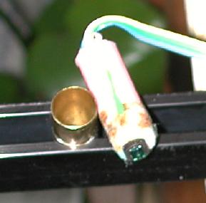
AFTER THE DEPLOYMENT all wands were inspected:
Without going into great detail about the testing, it appears the major
problem with the PARs was a leak between the diffuser and the shell
casing. Each sensor was taken apart and checked. Out of 72 sensors, 52
had signs of leaking. In some cases the leaking had not damaged the
sensor but others were totally damaged. The shells were checked for
leakage by attaching a hose line to the top of the shell, putting the
bottom of the shell in water then applying pressure to the hose
line. Bubbles in the water confirmed a leak.

PROBABLE CAUSE:
The diffuser was designed to be a press fit into the shell. For added
protection, a small amount of super glue was added when the two pieces
were put together. No leaks were found in the initial units made. The
problem may have been in the "production process". During the machining
of the diffuser there was the need to leave a small piece of material on
the edge of the diffuser. After the diffuser was mounted this small
piece was removed. We decided the easiest way to do this was to use a
lathe. It may have been the vibration of the lathe the caused the super
glue to fail. This is my best guess at what had happened.

FIXES:
- Epoxy glue and fill instead of super glue
- Bevel the edge of the bullets to improve gluing
- Reduce the size of the bullets
Instead of super glue we are running tests using a 2 part epoxy. The 4
shells made, with the epoxy, showed no leaks; however, the application
of the glue was done crudely (too much glue getting on diffuser
surface). The next step is to use a fine paintbrush to apply the glue,
test for leaks, if no leaks then use the lathe and repeat the leak
test. In addition, John did a new board layout which will allow us to
reduce the size of the shell such that PAR sensor will be encased
totally in the wand.

APOGEE ALTERNATIVE:
Apogee is a manufacturer of integrated quantum sensor 'wands' and is
willing to make a custom unit to our specifications using their diffuser
and sensors. This would not include calibrations. The cost per wand
would be ~$180 per wand in a quantity of a least 50.


MOS Mote Problems:
------------------
The version of MOS used for the Tsoil and PAR applications has low level
bugs that causes motes to lock up.  This effected the Tsoil deployment
dramatically, but not as severely for the PAR most likely because there
was no RF, and only 1 thread running.
	Wand-1	ttyS6, locked up on multiple occassions and required a manual reset.
	Wand-4	ttyS7, locked up on multiple occassions and required a manual reset.
	Wand-2	ttyS10, died and lost its program.

During roof tests at FL:
	Wand-1	ttyS6, died and lost its program and needed 'set_mos' to fix
	Wand-6	ttyS8, appeared to retain its program, but experienced outages/
			lockups on ttyS7.
	Wand-4	ttyS7, Strange: while trying to reprogram it to add 'W4' to
			the end of its message failed even though all other motes
			worked when this was done.....It did still work as before though;
			however, when first using a 'set_mos' before reprogramming worked!

For Reference,
West-Tree-0: Fir
Port	Wand#
ttyS7	wand4 	id=120
ttyS6	wand1	id=110
ttyS5	wand5	id=100

East-Tree-1: Spruce
ttyS10	wand2	id=150
ttyS9	wand3	id=140
ttyS8	wand6	id=130

 All wires from the bullets to the wand board had one of three color-coding patterns.
The I2C interface cables were all similar.
 The individual boards were mounted inside the wands to simplify cabling,
construction and minimize the size of board needed attached directly to
the mote. In practise the boards were installed upside-down in the
wands because of restricted space to attach the wires from the PAR
bullets. It was unclear whether having these boards mounted in the
wands reduced overall effort compared to a different solution of having
all the ADC's located with the motes. It did result in shorter analog
signal runs from the PAR though.
Alternative Accelerometers:
 The interface board included a Maxim MAX3221 RS232 Transceiver
( Data Sheet )
to allow signal translation for communications between the Mica2 and the
ADAM data system. This feature allowed the mote to be reprogrammed
directly from a PC without needing to rely upon a Crossbow programming
board. Although it was not done, the opportunity existed to change the
mote program while installed in a tree without having to include the
'over-air' programming code available with MOS, saving valuable code space.
The mote interface board included two TPS7603x linear low dropout voltage
regulators (LDO) by Texas Instruments
( Data Sheet ).
One provided the 3.3vdc needed for primary mote operations. The
second was optional (and not used in practise) to provide a lower
voltage to the wands. The rationale for that was to reduce the
dc-offset voltage for the level sensors (1/2 of vsupply, +/-
600mV=90degrees) so that a larger range than ~40 degrees could be
measured by the ADC limited to max 2.048v.
The mote interface board had other features that were not used
during the NIWOT07 PAR deployment: connections for interfacing
Mica2 internal adc channels 2-5, a connection for a Sensiron
SHT15 temp/rh sensor including a switched '+12vdc' FET that was intended to
cycle on/off an aspiration fan, and a connection for mote leds and
reset lines.
Shown below is the PCB layout of the mote interface board. Note the
jumper options. Also note the temporary labeling used to identify
that this box has calibrations for wand set #7 (see calibrations below).


