Air Sample Inlets for RAF Aircraft

(Dave Rogers, update Jan-2011)
EOL/RAF supports a variety of air sample inlet types, including simple goosenecks, solid diffuser, forward-facing cone, and others. RAF also flies custom inlets such as the Low Turbulence Inlet (LTI) and the University of Wyoming heated inlet and others.  In support of airborne research projects, RAF will configure the air sample inlets, install them and help connect them to instruments. To support the HIAPER aircraft, a new inlet was designed and built. It is called the HIAPER modular inlet (HIMIL) because its components can be customized to meet special needs.  HIMIL is available with two heights in order to sample outside of the flow boundary layer (more info). The tall version HIMIL has inlet tip 28 cm from aircraft skin, and short version tip is at 19 cm. This web page describes RAF's support for inlets and configuration options for the HIMIL.

HIMIL

The HIMIL is a flow-through type with diffusing nozzle upstream and converging nozzle downstream.  Photos show the separated components and interior. For the PACDEX project, four HIMIL inlets were used on HIAPER. A schematic view of their configurations and connections to instruments is shown in the graphic.

1, 2, or 3 sample tubes can be installed within one HIMIL. These tubes can be of different composition, and they can face upstream or downstream. Typical interior piping is stainless steel with diameters of 1/4" and 5/16" o.d.  These tubes can feed one or more instruments.

click for larger view
 
tall HIMIL click for larger view

Basic cleaning of the stainless steel tubing is done by pulling through a swab of acetone-soaked Kim-Wipe. Any additional or specialty cleaning is the responsibility of the instrument investigator.  Note that RAF has some data from a CO instrument that indicates a very large interference seemingly caused by some residue in the HIMIL. The origin of this interference may be due to acetone softening the sealant of the red dye that was used when the aluminum was anodized and later cleaned.

Icing of inlets in supercooled water clouds

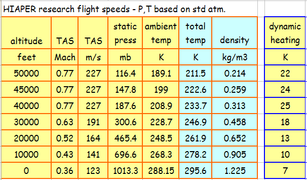
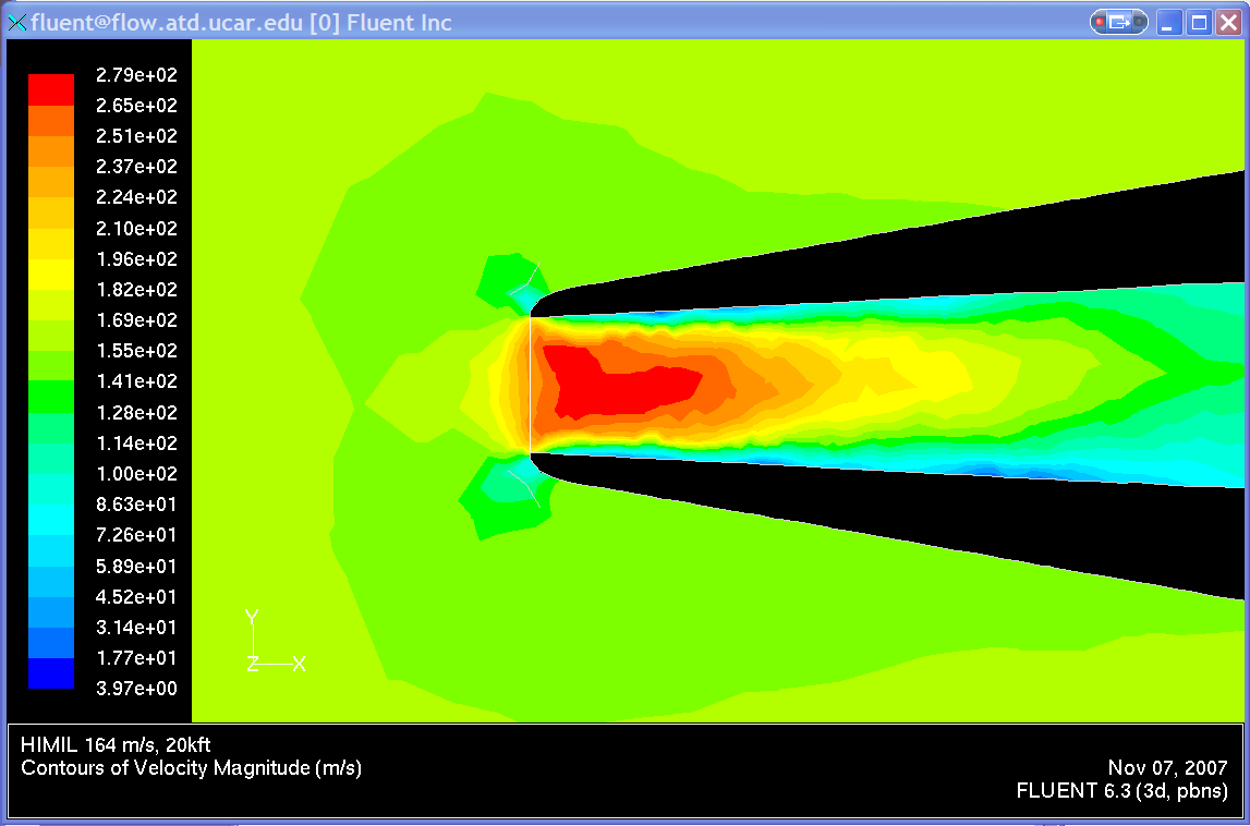
At typical research speeds for HIAPER, there will be ~15 to 20°C dynamic heating of the air as it adjusts to the aircraft speed. This heating can evaporate volatile components of aerosols. It also helps prevent icing of the inlet tip. There is also active electrical resistance heating of the inlet tip to prevent rime ice accumulation in supercooled water clouds.  The tip temperature is regulated to maintain +5°C.  Electrical heating can be switched off if desired.

Even with dynamic heating and a heated tip, it is possible for supercooled water to pass the tip, impact on the interior sampling tube and accumulate as rime ice, because the inner tubes are not heated.  This problem may be recognized by a reduction in sample pressure. Monitoring of sampling pressure is therefore suggested in order to determine if this problem occurs.

There may be additional dynamic pressure inside the HIMIL, depending on the orientation of internal sample tubes (pointing uptream, downstream or orthogonal to the flow) and sample pumping rates through those tubes.
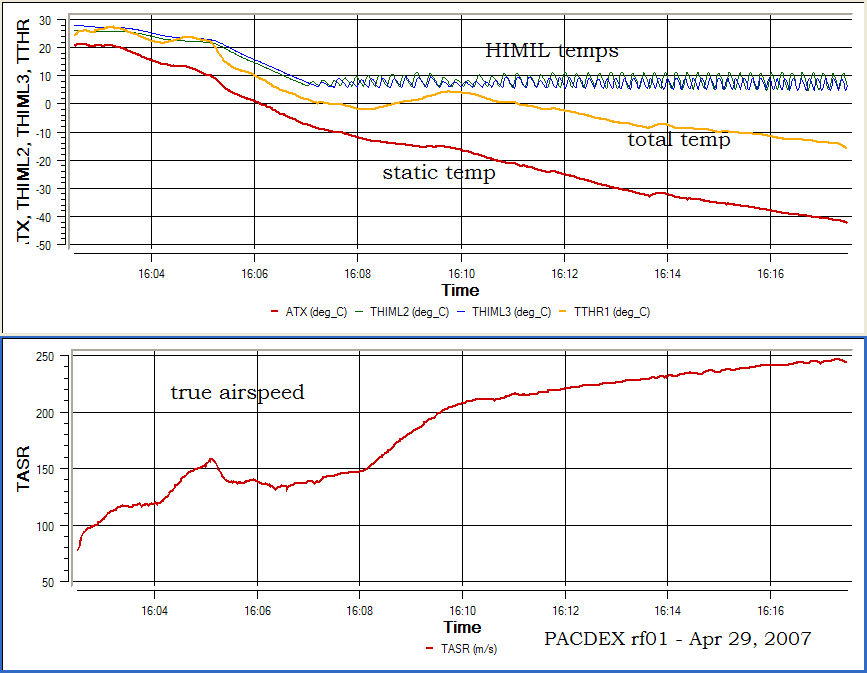
click to see dynamic heating
inlet temperatures during flight

Passing Efficiency of Aerosol Particles

Particle passing efficiency for the tip of the HIMIL was estimated by modeling the flow for conditions from sea level to 40 kft and research airspeeds appropriate for the GV at each altitude. Modeling was done with FLUENT software for both incompressible flow (k-omega turbulence scheme) and compressible flow (sstKW turbulence). The velocity at the inlet tip face was then used with Paul Baron’s spreadsheet to estimate the inlet sampling efficiency for aerosol particles of mass density 1.5 g/cm3.  The calculations suggest  ~100% passing of 1µm diameter particles from the tip to the inside of the HIMIL. The difference between incompressible and compressible flow appears to be small. Once past the tip, there are other effects of interior sample tubes, flow rates and downstream bends and fittings leading to instruments that will affect the sampling efficiency.  

ref  AeroCalc spreadsheet web site,  (cgs units row 576, “Inlet efficiency for an isoaxial horizontal sharp-edged inlet.”) 

(click for larger view)

Flow modeling studies at RAF are investigating the flow and thermodynamic fields for air sampling. Initial results show the interior velocity field when the ambient velocity is 164 m/s (typical for HIAPER at an altitude of 20 kft).  Particle trajectory studies are part of this work.
velocity (click for larger view)
velocity at tip
velocity in diffuser
pressure along axis