| jump to | LTI | SDI | CN |
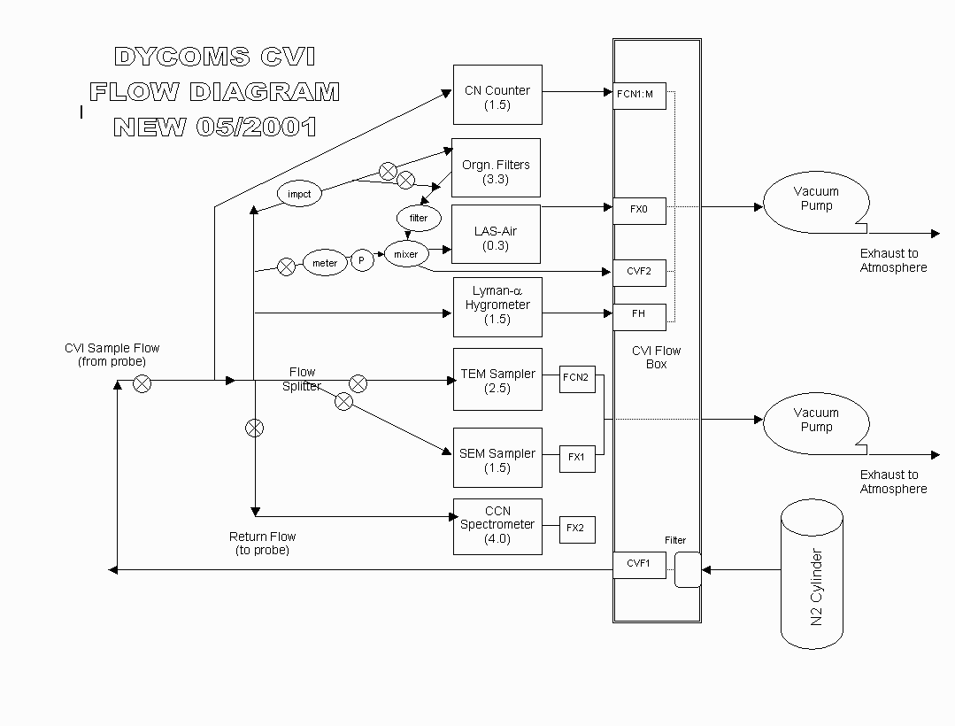
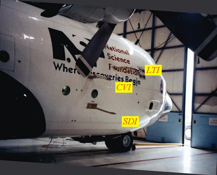
This document describes the air sampling arrangement for RAF, Princeton, Arizona, Oregon and Wyoming instruments on the NCAR C-130 during DYCOMS-II. Four inlets were used to bring ambient air samples inside the cabin: LTI, SDI, CVI, and CN-cone. The LTI, SDI, and CN-cone are briefly described here. The CVI instrument is described in other documentation and a CVI flow chart for the DYCOMS-II project. In addition to these particle inlets, there were aft-facing inlets for trace gas measurements (O3, DMS, CO, CO2); they are not described here. Only the CVI had the capability for heating to prevent icing in supercooled water clouds. The LTI, SDI and CVI were located near each other on the fuselage (see photo, compliments of Hiroshi Tagaki).
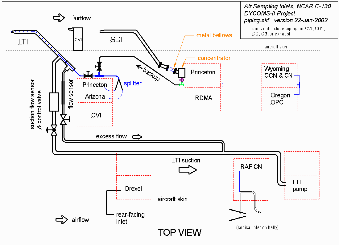
This diagram is a plan view of the piping in the C-130 cabin; the forward part of the cabin is to the left, and starboard is at the top. Both the LTI and SDI were operated iso-kinetically (velocity at the inlet tip matched the airspeed). A backup branch was installed to provide sample air from the SDI if the LTI failed during flight. In the case of LTI failure, the SDI could be selected to provide air to the front rack by closing the valve from the LTI and simultaneously opening the valve from the SDI. These were 3/8" stainless steel ball valves. In none of the DYCOMS-II flights did the LTI fail, and the backup branch was never used.
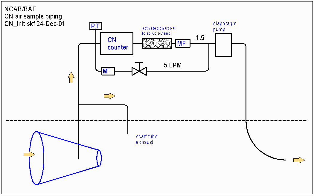
In this diagram, larger lines indicate larger diameter piping and greater flow rates.
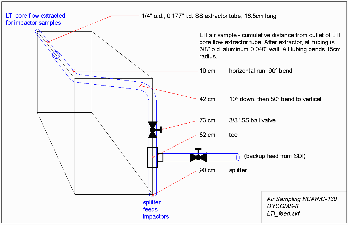
Sketch shows geometry of sample pick-off and tubing leading to splitter and impactors.
Total LTI flow was much larger than needed by the particle impactors, as shown in the following table; most of the flow was discarded as excess sample. Total flow (suction + excess) was automatically controlled to maintain isokinetic sampling at the inlet tip. Suction flow was automatically controlled to reduce turbulence in the diffuser inlet.
instrument |
location |
flow (LPM) |
| Princeton streaker | rack 1 | 2 |
| Arizona impactor & streaker | rack 1 | 4 |
| excess sample | LTI suction | 110 |
| TOTAL LTI | 116 |
Sample air from the SDI was divided among several different instruments. The total was 194 vLPM.
instrument |
location |
flow (LPM) |
| Princeton filters | rack 2 | 180 |
| RDMA | rack 2 | 5 |
| Wyo CCN | rack 3 | 6 |
| Wyo CN (2) | rack 3 | 2 |
| Oregon OPC | rack 3 | 1 |
| TOTAL SDI | 194 |
Flow rates for isokinetic sampling with the SDI were calculated over a range of airspeeds typical for the C-130, as shown in the following table. Isokinetic sampling conditions for 194 vLPM at the SDI tip were achieved for airspeeds ~113 m s-1. Non-isokinetic sampling occurred when the aircraft speed was different from 113 m s-1 or during occasional interruptions for changing sample media or servicing instruments.
| C-130 airspeed (m s-1) | 103 | 108 | 113 | 124 | 134 |
| SDI isokinetic flow (vLPM) | 177 | 186 | 195 | 214 | 231 |
Paul Baron's AeroCalc.xls spreadsheet (available from TSI) was used to estimate the iso-axial inlet sampling efficiency for the SDI 0.238" inlet at the same air speeds. Non-isokinetic conditions are estimated to cause errors less than 5% for sub-micron sampling as shown in table.
| SDI iso-axial inlet sampling efficiencies |
| particle diameter (µm) | 103 | 108 | 113 | 124 | 134 |
| 10 | 0.656 | 0.758 | 0.963 | 0.991 | 1.016 |
| 5 | 0.817 | 0.880 | 0.987 | 1.006 | 1.023 |
| 2 | 0.926 | 0.954 | 0.997 | 1.005 | 1.013 |
| 1 | 0.967 | 0.980 | 0.999 | 1.003 | 1.007 |
| 0.5 | 0.986 | 0.991 | 1.000 | 1.001 | 1.003 |
As shown in the detail view, this belly inlet drew air from the centerline of a forward-facing cone into a tube perpendicular to the cone axis. Compared to other inlets, this device has shown less susceptibility to produce CN as artifacts when droplets splash on the leading edge of the inlet.