Overview of PAM Power System

Station Power Requirements

A fully configured FLUX-PAM station consumes approximately 2.1 Amps at 12-VDC, or 50 Amp Hours per day. This nominal value can vary considerably depending upon the specific configuration.

In order to make accurate assessments of system power requirements, the best method is to measure the actual current output from the battery system into the station. Table 1 below summarizes nominal power requirements for typical sensors and PAMIII hardware.

Nominal Data System Power Requirements

Component

12-V Amps

Watts

Comments

Schroff VME Backplane:

Passive Termination

.4

4.8

Measured input to NCAR High Efficiency Power Supply


.85 @ 5

4.25

Backplane Alone, 5-Volt supply only,

No +12 or -12; =0

Schroff VME Backplane

Active Termination

20.5mA

.25

Measured input to NCAR High Efficiency Power Supply


36.4mA @ 5

.18

Backplane Alone, 5-Volt supply only,

No +12 or -12; =0

DMEM20 Pcmcia Drive

.11

1.2

without read/write


.06

.7

during read/write can be additional 40-60mA

EVE s/

DCOM332 CPU, NCAR-SIO, VADC-21 A/D, DMEM20 PCMCIA

.34

4.1

Measured with CPU running basic EVE code, .no I/O, Schroff Backplane, Active mode

EVE s/

DCOM332 CPU, NCAR-SIO, DMEM20 PCMCIA

.24

2.9

Measured with CPU running basic EVE code, .no I/O, Schroff Backplane, Active mode

EVE s/

DCOM332 CPU, NCAR-SIO

.16

1.9

Measured with CPU running basic EVE code, .no I/O, Schroff Backplane, Active mode

EVE w/

DCOM332 CPU, NCAR-Sio Panel, VADC-21 A/D, DMEM20 PCMCIA

.55

6.5

Measured with CPU running mathematical routine, PCMCIA i/o, minimal serial i/o.

`CDI' Power Supply (~70% efficient)

Power Supply Only

.04


powered off, led only

GOES/GMS Transmitter

.35

4.2

Transmitter in standby mode takes about .25W or less. Value shown represents one 30-sec transmit every 5-minutes (~3.3A)

Garmin GPS Receiver

.08

.96

Per Manuf. Spec. Sheet

Freewave L.O.S. Radio

~.11

1.3

Transmit=180mA, Receive=100mA

MorningStar PV Controller

~.01

.15

Quiescent current mostly for LEDs.

Nominal Sensor Power Requirements

Component

12-V Amps

Watts

Comments

NCAR Hygrothermometer

82mA

1.0


NCAR BandPass Hygrothermometer

60mA

.72

Power represents requirement for aspiration fan only. Sensor excitation provided by ATI sonic

ATI Sonic Anemometer

.9

11

Old-ancient `K-probes'

ATI Sonic Anemometer


1.2

New Version Probes, Manuf. Spec.

RMYoung Prop/Vane

80mA

1.0


ETI Precip Gauge

15mA

0.2


TDR/Trime Soil Moisture

.28

3.4


CS615 Soil Moisture

70mA

.85


Everest 4000.4GL IRT

10mA

.15


Gill Sonic R3

.3

3.6

Manuf. Spec.

Vaisala Barometer

25mA

0.3


REBs Net Radiometer


0


REBs HFT


0


REBs Soil Temp Probe

12mA

.15

2.5 VDC excitation, 100-ohm PRT in seried w/100-ohm divider

Campbell Logger

25mA

.3

Without Sensors

4-Component Radiometer

.4

4.8

Power represents requirement for 4 aspiration fans. Sensor excitation provided by Campbell.

Eppley PIR Pyrgeom.

12mA

.15

Estimate only


PhotoVoltaic System:

PAM stations are normally operated entirely off solar charged batteries. The Flux PAM-III station has relatively high power requirements for a solar charged system. In its Flux configuration, a PAM-III station may require between 4 to 6, 64Watt Solar Panels and 3, 100AmpHour batteries, depending upon the conditions and the sensor configuration.

The solar panels used are Solarex MSX-64 modules (data sheet included). In a simple, non-Flux configuration, the PAMIII station can be deployed with two of these panels mounted directly onto the main tripod assembly. In the Flux configuration two adjustable ground mounting stands are provided, each of which can accommodate 3 panels.

It is straightforward to make a quick estimate about how many solar panels are needed for a particular installation. Amp-Hour Load *1.25 / equivalent peak sun hours = minimum Photovoltaic capacity required. For example, if four panels (~14.4 amps under peak sun), are providing power for a 2-Amp continuous load, then a minimum of 4 hours of equivalent peak sun hours per day are needed. The solar industry typically uses a factor of 1.25, however, for field measurement systems like PAM, it is safer to size systems using a more conservative value such as 1.5.

Charging System:

NCAR uses a commercial photovoltaic charge controller built by MorningStar to manage the battery charging process. This charge controller is designed primarily for lead-acid type batteries, whether they are sealed, gel, or flooded wet-cell. It is a high-efficiency controller (~15mA current requirement) that is considered a constant voltage type of charge controller even though it uses a high-frequency pulse-width-modulation (PWM) technique to apply the actual current. (Note: Lead-Acid batteries typically work better with constant-voltage charging. When operating a solar charging system, `shunt' style charge controllers, which simply jumper the panel output to the batteries, should be avoided.) PWM according to some studies can increase battery life and help prevent sulfation of the electrodes. Like some other solar charge controllers, the MorningStar automatically compensates charging voltages for temperature variations.

Although PAM normally operates as a 12 volt system, the MorningStar also has built-in intelligence to regulate the system at either 12 or 24 volts. If the system is operated at 24 volts, both the battery bank as well as the solar panels should be operated at that level. This means that 3 sets of 2 solar panels would need to be put into a series/parallel connection, and either 2 or 4 batteries would be used. This means that a different set of "PV" and "battery" jumper cables would be needed than what is normally provided with PAM. Also, bypass diodes should be used to prevent back biasing between series connected solar panels. (Back biasing can happen when a significant portion of a solar panel becomes shaded and it shunts energy from others in the string. The excess current can cause overheating of the cells which may reduce efficiency and life of the panel.)

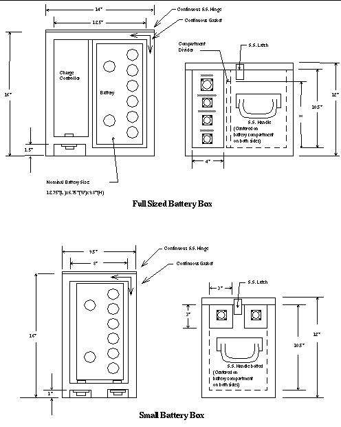
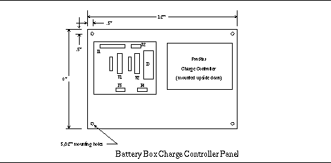
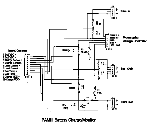
With PAMIII, the charge controller is mounted inside of a `full' sized battery box that includes a (single) battery compartment and a power monitor / fused disconnect board. One of these boards is included with each PAM station. For the Flux configuration, two additional `small' battery boxes are included which are jumpered in parallel from the main charging box. The power monitoring board of the charging system includes voltage dividers and shunt resistors used to send analog signals to EVE for recording battery voltage, temperature, load current and charging current. These signals are typically sampled through EVE's A/D0 port and can be used for ascertaining the health of the power system and its state-of-charge. In fact, the "Battery Test Results" shown in the next section were generated from data sampled by a PAM electronics box. A layout of the monitoring board and full sized battery box appears at the end of this section. If a PAM station goes down, one of the first places to look is at the fuses on this panel to see whether they blew or not.

Normally, the power provided to the `fused load' on the monitor board comes from the MorningStar's terminals labeled `load.' The `fused load' circuit on the monitor board gets distributed to the remote station electronics box `downstream' of the fuse and shunt resistor. The `load' terminals on the MorningStar are internally wired to an automatic low-voltage disconnect (also temperature compensated). This feature prevents batteries from becoming completely discharged and damaged or frozen as a result. Section 7.3 "Battery System" shows the discharge, and disconnect characteristics of two different batteries at room temperature and at 0-degrees. The MorningStar will allow a battery to go down to about 80% of its total depth of discharge. For a fully charged, new battery of the type used in PAM this should equate to about 60-80 AmpHours.

The MorningStar controller and the battery charge monitoring box can be used with other sources of power. For example it can be used with a DC power supply (as with the "A/C power supply system" noted in section 7.4), or a paralleled hybrid system such as Photovoltaic/Wind or Photovoltaic/Electrothermal. The only requirement is that the input current limit of the charge controller is not exceeded.

PAMIII Solar Battery Box

Battery Box Finish: Marine Grade 2-Part Epoxy manufactured by WesSystems Inc.

PAMIII Battery Box Charge Controller / Monitor Board Panel Layout:

PAMIII Battery Charge Monitor Board Schematic:

PAMIII Battery Charge Monitor Board Layout:

A/C Power Supply System for GAME

An A/C power supply system can be used for those installations where utility power is available. This has been only done once: in support of the Japanese GAME program. The power supply selected was a Kepco model FAW 15-3.4K that accommodates a wide input voltage/frequency range without the need to modify or change its settings. The output is 15-VDC. Two different transient/surge suppressors were included: an EFI model OEM120-20A and an OEM220-20A. The OEM120 model is nominally rated for 120VAC / RMS and should be used where the continuous single-phase input power does not exceed 130VAC. The OEM220 model is nominally rated for 220VAC / RMS and it should be used where the continuous single-phase input power does not exceed 250VAC. Both units will track lower voltages than their nominal ratings (such as 100VAC in Japan for the OEM120), as well as line frequencies including 50Hz and 60Hz. Because of space limitations in the power supply enclosure, it will be necessary to remove and replace the OEM transient protection when moving the station to locations where the line voltages change between the two nominal values.

It is recommended that the main battery charge controller box be used when operating with the A/C power supply system. The output of the Power Supply is provided via a 4-pin Amp style connector that can be directly connected to the battery box `Solar-In' receptacle. The output of the battery box `Fused-Load,' should be directly connected into the electronics box `Power-In' connector as usual. This method allows the Morning Star `solar' charge controller to float charge the battery, which acts as an Uninterruptible Power Supply when the A/C line goes down. The single battery should provide adequate backup for extended service outages of up to a maximum of 1.5 days, assuming a battery capacity of about 100 Amp Hours and a nominal station load of about 1.8-2.0Amps. As discussed in the photovoltaic section, the MorningStar charge controller will automatically disconnect the battery when the voltage drops to about 11.6VDC. The charging / discharging plots provided in the "battery" section should be typical of the performance that can be expected when using the A/C power supply system. The charging cycle shown indicates that a fully drained `100AmpHour' battery can be fully recharged within 20 hours of restoration of the A/C line power. Those measurements however, were taken with no `PAMIII' load bleeding off current from the battery. Under full `Flux-PAM' load, it should take about 40 hours to fully restore a totally discharged battery with this A/C supply. Note that under normal circumstances with few power outages, the stress on the battery is greatly reduced when using the A/C power supply system as compared to the typical photovoltaic application because the battery will essentially remain fully charged all of the time, and not experience frequent, high depth of discharge cycling. Batteries like that. In fact this is the typical of the `UPS' or automotive applications in which batteries often will last for several years.

The A/C power supply system is intended to be installed on the PAM-III tripod's vertical support using the `U-bolts' provided. The battery box should be placed on the tray adjacent to the A/C supply. It is extremely important that a good connection to earth ground is provided through the lug on the bottom of the box. Without that, the surge suppressors will provide no benefit and will not protect the system from line transients.

Specification Sheet: Kepco FAW 15-3.4K Power Supply

Specification Sheet: EFI OEM120/220-20A Transient Suppressor